

Once the path is proven and the band chosen, a point to point link still needs an antenna at each end, and for most hops the shortlist is a parabolic dish or a flat panel. The dish vs panel antenna choice trades gain and noise rejection against size, weight, wind load and how precisely the crew must aim.
Is a dish or a panel antenna better for a wireless link?
A parabolic dish gives more gain and a narrower beam from a larger aperture, so it suits long hops and crowded towers where interference rejection matters. A flat panel is smaller, lighter and more forgiving to aim, so it suits short hops and light mounts. Let the link budget decide: use the smallest antenna that leaves enough fade margin.

Dish vs panel antenna at a glance
The table compares the two designs in general terms for the same band; each antenna’s pattern sheet sets its real figures.
| Factor | Parabolic dish | Flat panel |
|---|---|---|
| Gain | Higher; grows with dish diameter | Lower; limited by the face area |
| Beamwidth | Narrow, a few degrees on larger dishes | Wider, more tolerant of movement |
| Interference rejection | Strong, especially shrouded designs | Moderate; hears more off axis |
| Wind load and weight | Larger projected area and heavier mount | Small, light, low profile |
| Best fit | Long hops, busy towers, tight fade margins | Short hops, subscriber ends, light poles |
Gain and beamwidth come from aperture size
Both designs are aperture antennas: gain depends on the area that captures the signal, measured in wavelengths. The MIT aperture antenna lecture gives directivity as 4 pi times the area times the aperture efficiency, divided by the wavelength squared, with efficiency about 0.65 in practice. For a typical tapered circular aperture it puts the half power beamwidth at 1.27 wavelengths divided by the diameter, in radians.
A worked example at 5.8 GHz, with stated assumptions: wavelength 299,792,458 / 5.8 billion = 0.0517 m, efficiency 0.65 for both antennas, a 0.6 m dish and a panel with a 0.3 m square face.
- Dish: area 3.1416 x 0.3 x 0.3 = 0.283 square meters; 4 pi x 0.283 / 0.0517 squared = 1,330; x 0.65 = 865, or 29.4 dBi.
- Dish beamwidth: 1.27 x 0.0517 / 0.6 = 0.109 radians, about 6.3 degrees.
- Panel: area 0.09 square meters; 4 pi x 0.09 / 0.0517 squared = 423; x 0.65 = 275, or 24.4 dBi.
- Panel beamwidth, treating the face as a 0.3 m aperture: 1.27 x 0.0517 / 0.3 = 0.219 radians, about 12.5 degrees.
The dish captures 3.1 times the area, worth 5.0 dB at each end, so 10 dB across the link. Doubling an aperture’s width adds about 6 dB and halves the beam, which is why panel antenna beamwidth stays wide. Real panels often fall below this because their feed network has loss, so budget with the data sheet gain.

Parabolic dish vs flat panel: how each is built
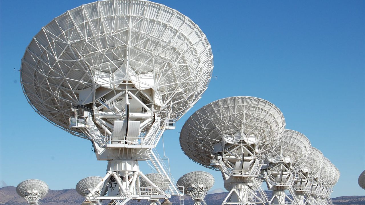
A parabolic dish has a feed at the focus of a curved reflector. The reflector turns the feed’s broad pattern into a narrow beam, and a larger reflector gives more gain without changing the radio. Many take a radome, and some add a shroud, a rim that reduces radiation to the sides and rear.
A flat panel packs an array of small elements onto a ground plane behind a flat radome. It is thin, often integrated with the radio, and quick to mount. A parabolic dish antenna for WISP backhaul usually comes in several diameters for the same band, so the gain can be sized to the hop; a panel is limited by how large a flat face is practical.
Both are commonly dual polarized; chain mapping is covered in antenna polarization explained.

Alignment tolerance in degrees
Half power beamwidth is measured between the points 3 dB below the peak. So an antenna pointed off axis by half its beamwidth has lost 3 dB, by definition. From the worked example:
- The 0.6 m dish loses 3 dB at about 3.1 degrees off axis.
- The 0.3 m panel loses 3 dB at about 6.3 degrees off axis.
- A 0.9 m dish, worked the same way, gives 32.9 dBi and a 4.2 degree beam, so 3 dB at 2.1 degrees.
The loss applies at each end, and a mount that twists in wind moves the beam the same way. A dish needs a rigid mount and a careful sweep; a panel tolerates a lighter bracket. The alignment sequence itself is in our guide on how to plan a point to point wireless link.
Side lobes and interference rejection
No antenna radiates only forward. The main lobe is surrounded by side lobes, and the same MIT lecture shows back lobes from feed spillover past the reflector edge and diffraction around it. Those lobes hear, and cause, interference off the path.
Illumination taper sets the trade. The lecture’s table for circular apertures:
| Illumination | Half power beamwidth | First side lobe | Taper efficiency |
|---|---|---|---|
| Uniform | 1.02 wavelength / diameter | 17.6 dB down | 1.00 |
| Moderate taper | 1.27 wavelength / diameter | 24.6 dB down | 0.75 |
| Strong taper | 1.47 wavelength / diameter | 30.4 dB down | 0.56 |
Lower side lobes cost some gain and widen the beam. Interference rejection comes from a narrow main lobe, low side lobes and a high front to back ratio. Shrouded dishes do best on all three, which is why they suit towers with many co-located links. For access points that must cover a wide area, the trade-offs change, as sector vs omni antennas explains.

Wind load and mounting
Wind force grows with the area facing the wind. In the worked example the 0.6 m dish presents about three times the face area of the 0.3 m panel, before shape, radome and shroud change the drag. Use the wind load figure on each data sheet, at the design wind speed for the site.
- Rate the mast, mount and structure for the total load of every antenna on them.
- Brace long pipe mounts so the dish does not twist off its 3 dB point in a gust.
- Bond the mount and cable shields to the site ground, as in our radio tower grounding guide.
Short links vs long links: which fits
Run the link budget with each candidate’s data sheet gain and pick the smallest antenna that leaves the fade margin the band needs.
- Short hop with margin to spare: a panel. Its wider beam forgives mount movement, and its lighter load suits poles and rooftops.
- Long hop or tight margin: a dish, sized to the gain the budget needs.
- Busy tower or noisy spectrum: a dish, preferably shrouded, even on a shorter hop.
- Short high band hop: check the band first; our 5 GHz vs 60 GHz wireless bridge guide covers when a different band beats a bigger antenna.
Neither antenna fixes a blocked Fresnel zone; raise the mounts or change the route first.
Where to find dish and panel antennas
The wireless network antenna category lists 2 GHz and 5 GHz dishes, dish radomes and dual polarity antennas. The point to point radios category and the wireless mounts category list the radios and brackets that go with them, all in the broadband and WiFi division.
For pricing and availability on a link, contact your sales representative through the Bursma contact page, or open a Bursma dealer account.
Frequently asked questions
What is the beamwidth of a panel antenna?
It depends on face size and band. From the aperture formula, a 0.3 m panel at 5.8 GHz has a beam of about 12.5 degrees, against about 6.3 degrees for a 0.6 m dish. Use the pattern sheet for the real figure.
How much more gain does a dish have than a panel?
Gain follows aperture area. In the worked example a 0.6 m dish captures 3.1 times the area of a 0.3 m panel, about 5 dB more at each end and 10 dB across the link.
Can I use a dish at one end and a panel at the other?
Yes, if the band and polarization match and the budget closes with both gains added.
Why are dish antennas harder to align?
Their beam is narrower. A 0.6 m dish at 5.8 GHz loses 3 dB about 3 degrees off axis, and a side lobe can be mistaken for the main lobe during the sweep.