

A tower is the tallest conductor on most WISP and two-way radio sites, and every cable on it leads to equipment someone paid for. Radio tower grounding is what gives a surge a path to earth outside the building and keeps the tower, the coax and the electrical system at one potential. This guide explains the parts of a tower ground system and where each bond goes, and it is clear about who designs and approves it: a licensed engineer and the authority having jurisdiction (AHJ).
How is a radio tower grounded?
Radio tower grounding bonds each tower leg to buried ground rods joined by a ring conductor, bonds the coax shields with grounding kits near the antenna, at the tower base and at the building entry, and ties everything at one entrance panel to the building’s grounding electrode system. An engineer designs it and the AHJ approves it.

What radio tower grounding has to do
Grounding does three jobs. It gives lightning and surge current a short, low-impedance path into the earth, it keeps every metal part of the site at nearly the same voltage during that surge, and it keeps the surge current out of the radios and switches inside.
The second job matters most to equipment. Damage often comes from a voltage difference between two systems, such as a tower ground and a building ground that are not bonded together. That is why the goal is a single-point ground: one bonded system, with every cable entering at one place.
Grounding reduces risk; it does not make a site lightning-proof. A direct strike can still damage antennas and radios at the top of the tower.

The communication tower ground system: rods and ring
A communication tower ground system starts below grade. A ring of bare conductor buried around the tower base joins a set of driven ground rods, and the ring is bonded to the building’s ground system so the two act as one.
For a sense of scale, the FAA’s standard for its own sites, FAA-STD-019f on lightning protection, grounding and bonding, sets these minimums for an FAA earth electrode system:
- Copper or copper-clad steel rods at least 10 feet long and 3/4 inch in diameter.
- Rods spaced no closer than one rod length, nominally two to three rod lengths apart.
- A closed loop of bare 4/0 AWG copper at least 2 feet below grade, below the frost depth.
- Rods 2 to 6 feet beyond the foundation, with a resistance target no higher than 10 ohms.
Those figures are FAA minimums for FAA facilities, quoted to show what a designed system looks like. Your site’s rod count, depth and conductor size come from the engineer’s design, the soil and the code the AHJ enforces.
Bonding the tower legs
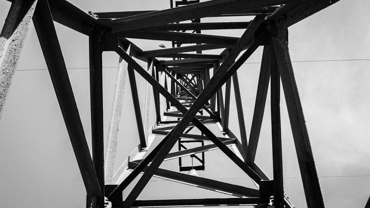
Common practice connects each leg of a self-supporting tower, or the base of a guyed mast, to the ring with its own conductor. FAA-STD-019f calls for at least two down conductors on towers other than small pole-type towers, bonded to each tower section and secured to the outside of the legs at intervals of no more than 3 feet.
- Run conductors straight down and toward the ring; the FAA standard allows no bend sharper than 90 degrees or tighter than an 8 inch radius.
- Bond to clean, bare metal, and seal the joint against weather.
- Mind dissimilar metals: the FAA standard limits which metal pairs may be bonded directly, so use connectors listed for the metals they join.
- On guyed towers the guys need grounding too; the FAA standard points to the TIA-222 tower standard for it.
The structure choice itself, and why guyed and self-supporting towers differ, is in our guyed vs self-supporting tower comparison.
Coax shield grounding at the top, bottom and entry
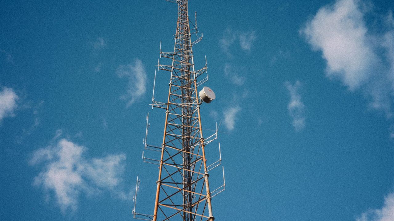
A coax or shielded Ethernet line on a tower picks up surge current along its whole length. Common practice is to bond the shield with a grounding kit in three places:
- At the top, near the antenna, bonded to the tower.
- At the bottom, just above where the line leaves the tower, bonded to a ground bar on the tower. FAA-STD-019f puts this plate above the cable path at the bend near the tower base.
- At the building entry, on the entrance panel.
Use kits sized for the specific cable, weatherproof each one as its instructions say, and route each kit lead downward without sharp bends. Tall towers may need more kits along the run; the count comes from the cable maker’s instructions and the engineer.
Tower grounding points compared
| Location | What gets bonded | Typical hardware | Who sets the detail |
|---|---|---|---|
| Below grade | Rods and ring around the tower | Ground rods, bare copper loop, welded or listed connections | Engineer, soil, AHJ |
| Tower legs | Each leg or the mast base to the ring | Down conductors, leg clamps | Engineer, tower maker |
| Tower top | Coax and cable shields near the antenna | Shield grounding kits | Cable maker, engineer |
| Tower base | All shields leaving the tower | Ground bar on the tower, shield kits | Engineer |
| Building entry | Shields, surge protectors, the ring and the building ground | Entrance panel, surge protectors | Engineer, electrician, AHJ |
The entrance panel and surge protection
The entrance panel, sometimes called a bulkhead plate, is the single point where every tower cable enters. FAA-STD-019f places it outside the building or within 2 feet of the exterior wall inside, specifies a copper or aluminum plate with spare positions, and, where surge protectors are fitted, places them on the antenna side of the plate.
Bond the panel to the ring and to the building’s grounding electrode system with short, straight conductors. Fit a surge protector to every coax and Ethernet line that crosses it, and protect the AC side as well; our guide to power conditioners vs surge protectors explains what plug-in protection covers. A licensed electrician makes the connection to the electrical service.
Codes, standards and who decides
In the National Electrical Code, Article 810 covers radio and television equipment, including antenna systems, and Article 820 covers community antenna television and radio distribution systems. The basic Article 810 rules for masts and lead-ins are summarized in our guide on how to ground a TV antenna and mast; a tower site adds the ring, leg bonding and entrance panel on top of them.
Carriers and radio networks often publish their own site grounding standards, and the FAA standard above applies only to FAA facilities. Which documents govern your site is a decision for the engineer and the AHJ. Keep the design and every inspection on file.
Tower lightning protection limits and inspection
Tower lightning protection is a system, and it degrades. Clamps loosen, connections corrode and cable runs get added without kits.
- Inspect bonds, kits and the entrance panel on a schedule and after major storms.
- Bond every new cable at the top, the base and the entry before it goes into service.
- Never climb or work on a tower when storms are near, and use trained climbers with fall protection.
Where to find towers and site hardware
The wireless network towers category lists tower sections, bases and self-supporting towers, part of the broadband and WiFi division. The same structures appear in the antenna, tower and satellite division. For grounding materials to match an engineer’s design, contact your sales representative through the Bursma contact page, or open a Bursma dealer account.
Frequently asked questions
Does a radio tower need its own ground rods?
Usually yes, as part of a ring around the tower base. Those rods must be bonded to the building’s grounding electrode system so the two do not sit at different voltages during a surge.
How many ground rods does a tower need?
There is no single number. The count, spacing and depth depend on the tower, the soil and the design the engineer produces for the AHJ.
Is grounding the coax at the building entry enough?
Not on a tower. Common practice bonds the shield near the antenna and at the tower base as well, so surge current leaves the cable before it reaches the building.
Does grounding protect a tower from a direct strike?
It gives the strike a path to earth and limits the damage, but antennas and radios on top can still be destroyed. Grounding lowers the risk to the building and the gear inside.