

A point to point link either holds through a wet spring night or it does not, and most of the difference is decided before anyone climbs a tower. This guide covers how to plan a point to point wireless link the way a WISP crew or integrator actually builds one: prove the path, run the numbers, pick the band, then mount and align. The formulas below come from ITU-R propagation recommendations and the band rules from the FCC, so you can check every figure against the source.
How do you plan a point to point wireless link?
To plan a point to point wireless link, prove the path, run the numbers, pick the band, then mount and align. Keep at least 60% of the first Fresnel zone clear, calculate free-space path loss, build a link budget with a fade margin suited to the band, confirm the FCC rules for 5, 60 or 70/80 GHz, then align and compare the received level to the budget.
Line of sight is more than a clear view
Seeing the far end from the near end is visual line of sight. A radio link needs more than that: the space around the direct path, the first Fresnel zone, also has to be mostly clear. Terrain, rooftops or trees that intrude into that zone add diffraction loss even when the beam itself is not blocked.
ITU-R Recommendation P.530 gives the radius of the first Fresnel zone as F1 = 17.3 × √(d1 × d2 / (f × d)) metres, where f is the frequency in GHz, d is the path length in km, and d1 and d2 are the distances in km from each end to the obstruction (P.530, equation 3). The zone is widest at mid-path, so check obstacles near the middle carefully. Two worked examples from that formula:
- A 5 km link at 5.8 GHz has a mid-path Fresnel radius of about 8.0 m.
- A 1 km link at 60 GHz has a mid-path Fresnel radius of about 1.1 m.
How much of that zone must be clear? P.530 states that diffraction theory calls for a clearance above ground of at least 60% of the radius of the first Fresnel zone to achieve free-space propagation conditions. For the 5 km example, that is roughly 4.8 m of clear space below the beam line at mid-path. P.530’s planning procedure goes further: in the absence of local data it uses an effective Earth-radius factor of k = 4/3 and 1.0 F1 clearance over the highest obstacle as its first step (P.530, section 2.2.2.1).
Three field notes follow from this:
- The Earth bulges. On longer paths the curvature of the Earth raises the ground at mid-path relative to the beam. Path profile software applies the k-factor for you; on short urban hops it rarely matters.
- Measure obstacles honestly. P.530 notes that above about 13 GHz the accuracy of your obstacle height estimate starts to approach the size of the Fresnel zone itself, and that this uncertainty should be added to the clearance.
- Plan for growth. A tree line that clears the zone in January may not clear it in July, and a vacant lot on the path can become a building.

Free-space path loss
Even over a perfectly clear path, signal spreads out with distance. ITU-R Recommendation P.525 gives the free-space basic transmission loss between isotropic antennas as L = 32.4 + 20 log f + 20 log d dB, with f in MHz and d in km (P.525, equation 4). Working that formula:
- 5 km at 5,800 MHz: about 121.6 dB.
- 1 km at 60,000 MHz: about 128.0 dB, before any atmospheric absorption.
Because distance enters as 20 log d, doubling the path length adds about 6 dB of loss, and the same is true of doubling the frequency. That is why high-band links are short and why antenna gain matters so much at both ends.

Link budget and fade margin
The link budget is simple addition in decibels. Start with the transmitter’s output power, add the transmit antenna gain, subtract any cable or connector loss on the transmit side, subtract the path loss and any atmospheric loss, add the receive antenna gain and subtract the receive-side losses. The result is the expected received signal level.
Fade margin is the difference between that expected level and the receiver sensitivity the radio’s data sheet lists for the modulation and throughput you need. Higher-order modulation needs more signal, so the margin at full capacity is smaller than the margin at the radio’s most robust rate.
The margin exists to absorb fading. P.530 lists the mechanisms a terrestrial link designer has to account for, including diffraction fading when the path is obstructed under adverse refraction, multipath fading, and attenuation from rain and other precipitation. It also notes that rain attenuation can be ignored below about 5 GHz but must be included at higher frequencies, where its importance increases rapidly (P.530, section 2.4). In practice that means the margin you need depends on the band: a link above that point needs its margin sized for local rain, which P.530 calculates from regional rain-rate data.
When the link is up, compare the received level to your budget. A level far below the calculation usually means a misaligned antenna, an obstructed Fresnel zone or a cabling fault, not a bad radio.

Choosing a band: 5 GHz, 60 GHz and 70/80 GHz
5 GHz unlicensed (U-NII)
The FCC’s U-NII rules cover 5.15-5.25, 5.25-5.35, 5.47-5.725 and 5.725-5.850 GHz (47 CFR 15.407). In the 5.725-5.850 GHz band, conducted output power is limited to 1 W, but fixed point-to-point devices may use antennas with more than 6 dBi of gain without reducing transmitter power (15.407(a)(3)). The rule defines point-to-point narrowly: it excludes point-to-multipoint systems, omnidirectional applications and multiple collocated transmitters sending the same information, and it makes the operator, or the installer when the equipment is professionally installed, responsible for keeping high-gain systems point-to-point. In 5.15-5.25 GHz, fixed point-to-point access points are limited to 1 W conducted and may use antennas of up to 23 dBi without a power reduction (15.407(a)(1)).
5 GHz handles distance well and sits near the frequency where P.530 says rain starts to matter, so rain fade is modest. The trade-off is that it is unlicensed and widely used, so plan channels around what a spectrum scan shows at both ends.
60 GHz unlicensed
The FCC’s rule for 57-71 GHz (47 CFR 15.255) allows a fixed point-to-point transmitter located outdoors an average power of up to 82 dBm EIRP, reduced by 2 dB for every dB that the antenna gain is less than 51 dBi (15.255(c)(1)(ii)). The catch is the atmosphere. ITU-R Report F.2107 states that outdoors, gaseous absorption attenuates the signal by roughly 10 to 15 dB/km in addition to free-space loss near 60 GHz, and that rain has the greatest impact on signals in the 60, 70, 80 and 95 GHz bands.
The same report notes the upside: the absorption and the narrow beams of high-frequency antennas cut interference between neighbouring links and allow dense frequency reuse. A 60 GHz point to point radio is a strong fit for short, high-capacity hops between buildings or across a campus. For longer paths, or where rain outages are not acceptable, run the budget with the oxygen loss and a rain margin added before you commit.
70/80 GHz light licensing
In the 71-76 GHz and 81-86 GHz bands, the FCC issues nationwide non-exclusive licenses (47 CFR 101.1501), and each link is registered individually. Under 47 CFR 101.1523, the applicant supplies an interference analysis for the proposed link, and first-in-time registered links receive protection against harmful interference from later ones. F.2107 notes that gaseous absorption in the 70/80/95 GHz bands is negligible, so these links reach farther than 60 GHz, but rain still dominates their fade budget.
Mounting and alignment
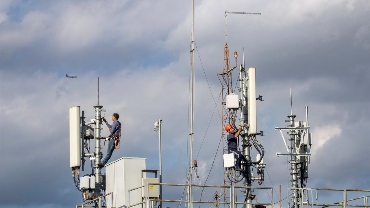
The narrower the beam, the less movement a link tolerates. F.2107 notes that antenna beamwidth is inversely proportional to operating frequency, so a 60 GHz or 80 GHz dish of a given size has a much tighter beam than a 5 GHz antenna of the same size.
- Mount rigidly. Use a pipe and bracket rated for the antenna and its wind load, keep the mount close to the structure, and avoid long unbraced masts that twist or sway.
- Match polarization at both ends before fine alignment.
- Align in stages. Set the bearing and elevation from the path plan, then fine-tune one end at a time using the radio’s received signal reading, sweeping past the peak in both axes and settling on the centre.
- Check against the budget. If the peak you find is well below the predicted level, you may be on a side lobe; keep sweeping for the main lobe.
- Finish the site. Weatherproof every outdoor connector, bond the mount and cable shields to the site grounding, and record bearings, elevations and received levels for the next crew.
If the link needs a new or taller structure, check the FAA rules first: 14 CFR 77.9 requires notice to the FAA for any construction or alteration more than 200 ft above ground level, and for shorter structures near airports and heliports.

How to plan a point to point wireless link: the order of work
- Confirm both endpoints, mounting heights and the capacity the link must carry.
- Draw the path profile and check 60% first Fresnel zone clearance at the worst point, allowing for Earth curvature and future obstructions.
- Calculate free-space path loss, add atmospheric and rain allowances for the band, and build the link budget.
- Choose the band and antennas so the fade margin at the required modulation suits the band’s fading.
- Confirm the band’s FCC rules: point-to-point use for U-NII power limits, the EIRP limit at 60 GHz, link registration at 70/80 GHz, and FAA notice if a structure is involved.
- Mount, align, compare the received level to the budget and document the result.
Frequently asked questions
How much Fresnel zone clearance does a point to point link need?
ITU-R P.530 calls for clearance of at least 60% of the first Fresnel zone radius to achieve free-space propagation conditions. The zone is widest at mid-path, so check obstacles there carefully. For a 5 km link at 5.8 GHz, the mid-path radius is about 8.0 m, so roughly 4.8 m below the beam line must be clear.
Does rain affect point to point wireless links?
It depends on the band. P.530 says rain attenuation can be ignored below about 5 GHz but must be included at higher frequencies, where its importance increases rapidly. ITU-R Report F.2107 notes that rain has the greatest impact on the 60, 70, 80 and 95 GHz bands, so links there need a fade margin sized for local rain.
Do I need a license for a point to point wireless link?
Not in the 5 GHz U-NII bands or at 57-71 GHz, which are unlicensed, though each has FCC power and antenna rules. In the 71-76 GHz and 81-86 GHz bands the FCC issues nationwide non-exclusive licenses and each link is registered individually, with first-in-time links protected against harmful interference from later ones.
How do you calculate fade margin for a wireless link?
Build the link budget first: transmitter power plus antenna gains, minus cable losses, path loss and atmospheric loss, gives the expected received signal level. Fade margin is the difference between that level and the receiver sensitivity the radio’s data sheet lists for the modulation and throughput you need.
Why is 60 GHz used for short links?
Near 60 GHz, gaseous absorption attenuates the signal by roughly 10 to 15 dB per km on top of free-space loss, according to ITU-R Report F.2107. That makes 60 GHz a strong fit for short, high-capacity hops between buildings or across a campus. For longer paths, run the budget with the oxygen loss and a rain margin added before you commit.
Where to buy point to point radios
Bursma Distributing supplies wireless networking gear wholesale to WISPs, installers and integrators. Browse the radios category and the wider Broadband - WiFi division for radios, antennas and the mounting and cabling that go with them. Dealers see their own pricing and stock levels in Shop Online after logging in. If you are not a Bursma customer yet, open a dealer account, or call 616-831-0080 and talk to your sales representative about the link you are planning.
Sources
- ITU-R Recommendation P.530-19, Propagation data and prediction methods required for the design of terrestrial line-of-sight systems
- ITU-R Recommendation P.525, Calculation of free-space attenuation
- ITU-R Report F.2107, Characteristics and applications of fixed wireless systems operating in the 57 GHz to 95 GHz band
- 47 CFR 15.407, General technical requirements for U-NII devices (Cornell Legal Information Institute)
- 47 CFR 15.255, Operation within the band 57-71 GHz (Cornell Legal Information Institute)
- 47 CFR 101.1501, 71-76 GHz and 81-86 GHz licensing (Cornell Legal Information Institute)
- 47 CFR 101.1523, Link registration (Cornell Legal Information Institute)
- 14 CFR 77.9, Construction or alteration requiring notice (Cornell Legal Information Institute)