

One antenna or cable drop, three TVs, and a splitter in the middle. It looks like the easiest part of the job, yet a splitter that is too big, a port left open or an amplifier in the wrong place can cost more signal than the cable run. This guide shows how to install a coax splitter, how to read its loss, and where amplifiers and grounding sit in the layout.
How do you install a coax splitter?
Connect the cable from the antenna, dish or ground block to the splitter’s IN port, then run one cable from each OUT port to a TV or tuner. Use a splitter with no more ports than you need, cap unused ports with 75 ohm terminators, and put any amplifier before the split.
2 way vs 4 way splitter: size it to the job
Count the outlets that need signal now, plus any you will wire for later. Then pick the smallest splitter that covers them. Every output port takes its share of the power whether a TV is connected or not, so a 4-way feeding two TVs loses as much at each port as one feeding four.
- 2-way: two outlets, or one TV plus a second tuner.
- 3-way: three outlets; check whether it is balanced or unbalanced (see the table).
- 4-way: four outlets, or three with one planned.
- 8-way: whole-house distribution, usually after an amplifier.
Cable choice matters as much as the splitter on long runs; our guide to RG6 vs RG59 coax covers loss by frequency.

Coax splitter signal loss per port
A perfect, lossless splitter divides power equally, so each of N outputs gets 1/N of the input. In decibels, loss is 10 times the base-10 logarithm of the power ratio, as the Harvey Mudd College decibel lecture notes define it. For a 2-way, 10 x log10(2) = 3.01 dB: each port gets half the power.
Real splitters lose a little more, and more at higher frequencies. The typical figures below are common markings, not a specification; read the loss printed on the device you fit.
| Splitter | Ideal loss per port | Typical marked loss | Share of input power |
|---|---|---|---|
| 2-way | 3.0 dB | About 3.5 dB | Half |
| 3-way balanced | 4.8 dB | About 5.5 to 6 dB | One third |
| 3-way unbalanced | 3.0 / 6.0 dB | About 3.5 dB on one port, 7 dB on two | Half, then a quarter |
| 4-way | 6.0 dB | About 7 dB | One quarter |
| 8-way | 9.0 dB | About 10.5 to 11 dB | One eighth |
The 8-way and unbalanced 3-way rows assume they are built from 2-way stages of about 3.5 dB each: three stages make about 10.5 dB, two make about 7 dB. Use the unbalanced 3-way’s low-loss port for the longest run.
How to install a coax splitter, step by step
- Unplug any amplifier or power inserter before you open the line.
- Mount the splitter indoors where possible, on a solid surface near the entry or distribution point, so the ports are not carrying the cable weight.
- Connect the source to IN. The antenna, dish or ground block cable goes to the port marked IN. Fed through an OUT port, a splitter sends little signal to the other outputs.
- Fit one run per OUT port. Use compression F connectors on every end; our guide to compression vs crimp F connectors covers stripping and tightening.
- Label each run at the splitter with the room it feeds.
- Cap any spare port, then restore power and test.
Keep the coax clear of power wiring and tight bends. At the wall, an F-81 keystone insert finishes each outlet neatly.
Terminate unused splitter ports
An open port is an unmatched 75 ohm line. Signal reflects from it, and an open port can let outside interference into the system. Screw a 75 ohm terminator onto every port you are not using, including ports left for future rooms.
Capping a port does not recover its share of the power; the splitter’s loss is fixed by its design. If ports will stay empty for good, fit a smaller splitter instead.
Put the amplifier before the split
An amplifier boosts whatever arrives at its input, including noise. Placed after the splitter, it amplifies a signal that has already lost a quarter or more of its power, so it can only serve one leg. Placed before, it lifts the signal once, and every output starts higher.
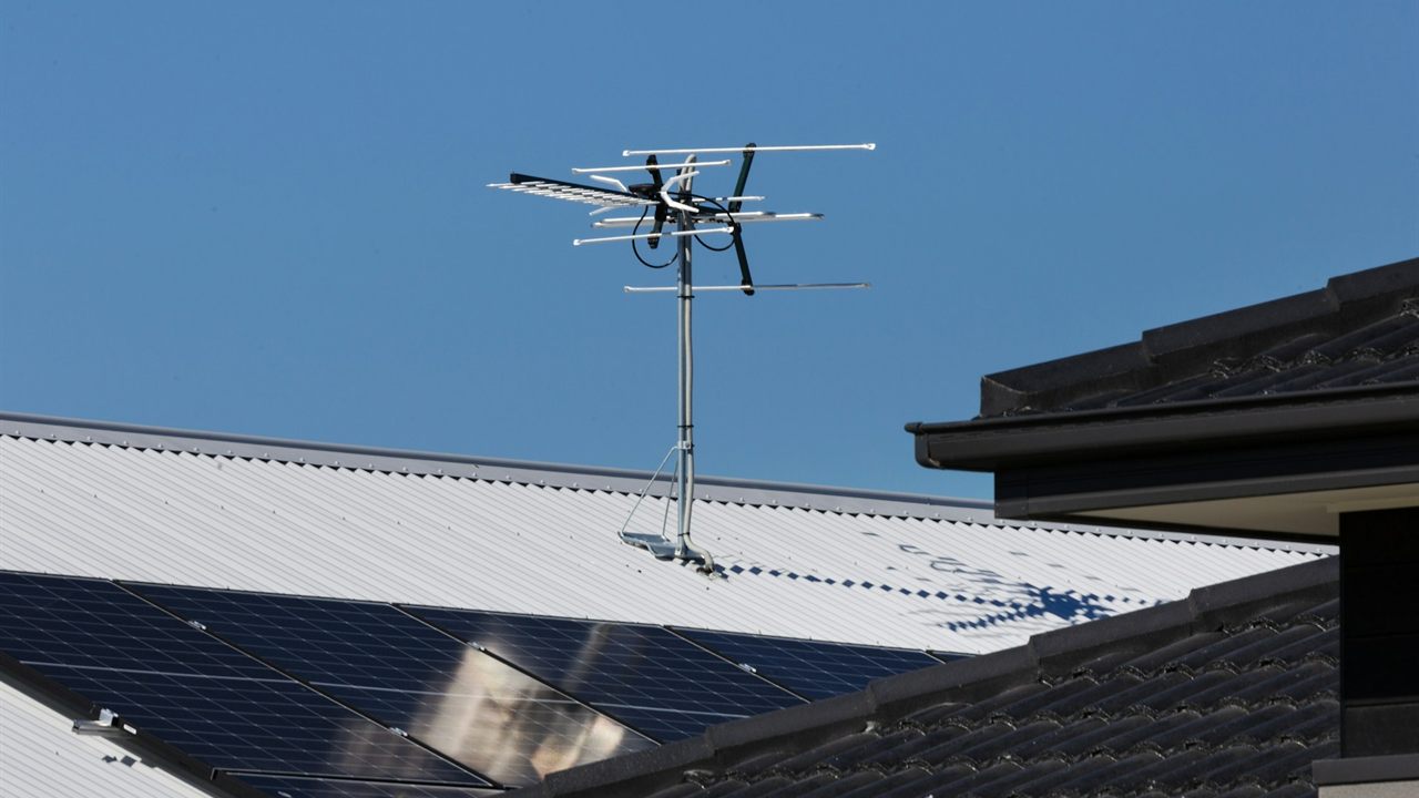
On antenna systems, a mast preamplifier at the antenna sets the noise performance before the downlead and splitter losses; our guide on how to choose an antenna preamplifier works through that cascade. Many preamps are powered over the coax, so place the power inserter so DC reaches the preamp without passing through a splitter port that blocks it, or use a splitter marked as power passing on that port.
A distribution amplifier with several outputs is the other route on large jobs. Do not stack amplifiers to make up for an oversized splitter: too much gain can overload tuners.
Check the frequency rating, then test
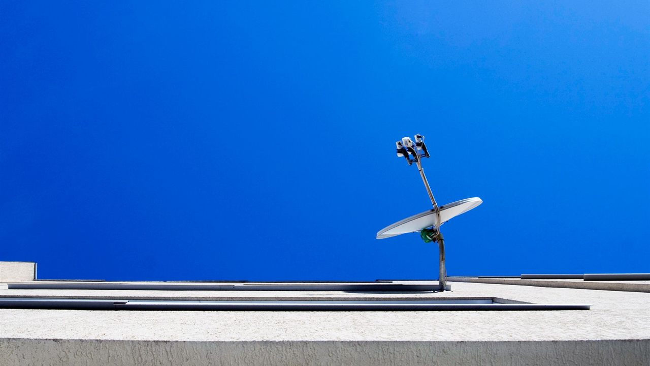
Every splitter is marked with the frequency range it passes. For an over the air antenna, check that it covers the TV bands in use. Satellite needs a splitter rated for the dish’s frequencies and, usually, DC power passing for the LNB. Cable and internet drops may need a splitter suited to the service.
Once the splitter is in and the drop is grounded, run a channel scan on each TV and compare the signal readings with those from a direct connection where you can. A marginal channel that disappears after the split points to a smaller splitter, a shorter run or an amplifier ahead of the split.
Ground the coax before the splitter
The splitter is not the grounding point. Where coax enters the building, the shield should be bonded at a grounding block as close as practicable to the point of entrance, and the splitter then goes on the inside of that block. Some splitters have a ground lug, but bonding at the entry still comes first.
Our guide on how to ground a TV antenna and mast covers the bonding conductor, the block and the mast. If a splitter must sit outside, use one rated for outdoor use, point the ports down or add drip loops, and seal the connectors.
Where to find coax, connectors and amplifiers
The Bursma coax category lists RG6 in reels, including dual, messenger and direct burial types. F connectors are in the connectors category, keystone F inserts in the wall plates and inserts category, and preamplifiers in the antenna preamps category, all part of the antenna, tower and satellite division.
For pricing and availability, ask your sales representative through the Bursma contact page. If you install for a living, apply for a Bursma dealer account.
Frequently asked questions
How much signal does a coax splitter lose?
At least 10 x log10 of the number of outputs: 3 dB for a 2-way, 6 dB for a 4-way, 9 dB for an 8-way. Real splitters lose a little more, so read the loss marked on each port.
Does a 4 way splitter lose more signal than a 2 way?
Yes. A 4-way gives each port about a quarter of the input power, against half for a 2-way, whether or not every port is used.
Do unused splitter ports need to be capped?
Yes. A 75 ohm terminator stops reflections from the open port and helps keep outside interference out. It does not reduce the splitter’s loss.
Should the amplifier go before or after the splitter?
Before. One amplifier ahead of the split raises the signal for every output. After the split it serves only one leg and amplifies a signal that has already lost power.